SOPC PCI Express Family
Intel (Altera) Fpga Based PCI Express cards with drivers
GEB PCI Express Family Overview
The Geb PCI Express cards family add to the PCI Express architecture the powerfull of Altera FPGA that allow a flexible I/O system.
The I/O speed capability goes up to 260Mbytes/sec (Full Duplex Read/Write DMA Burst Access).
Altera QSYS allow easy and quick system design. Windows Seven, XP, Linux driver are available on basic systems developed by GEB. You can buy together any PCIe boards samples a RDK (Rapid Development Kit) that includes programmed board and windows executable, allowing You to an immediate use. You can also modify the system using Altera QSYS or SOPC Builder to customize the boards to Your application in few time. The PCIe boards can be reprogrammed using USB Blaster and GEB MTA adapter (Mini Tap Adapter).
Family features:
- Up to 10 Mbytes/sec transfer rate in single random read/write access
- Up to 150Mbytes/sec transfer rate in burst (DMA) half duplex read or write access
- Up to 260Mbytes/sec transfer rate in burst (DMA) full duplex read and write access
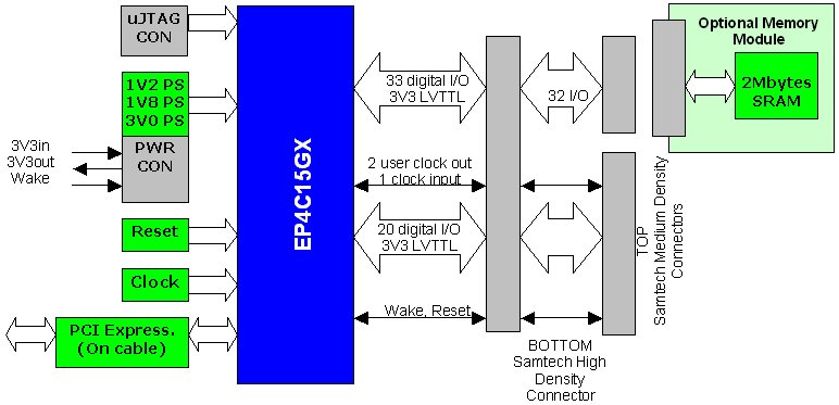
- 53 LVTTL 3V3 digital I/O user channels, each one with independent sense, drive, bi-directional, and tri-state capabilities
- 2 User LVTTL output clocks (1 output with dedicated PLL)
- 1 User LVTTL input clocks with dedicated PLL
- Single 3V3 Power Supply
- Peripheral to host wake up support
- Remote host to peripheral power on support
- Hot insertion support (PCIe downstream only)
- Fpga resources:EP4GX15BF14C7N version: 14,400 logic elements, 540Kbits RAM, 3xPLL
- EP4CGX30BF14C6N version: 29,440 logic elements, 1080Kbits RAM, 2xPLLs, 80 Multipliers 18X18
- Boot device
- Power on monitor and reset circuitry
- One test access port (TAP) to control the I/O channels
- On board crystal oscillator
- Boundary-scan, JTAG/IEEE 1149.1 standard compatible
PCI Express Features
PCI (Peripheral Component Interconnect) Express (name PCIe) is a scalable I/O serial bus technology set to replace parallel PCI bus. In the next part of 2004 PCI Express slots began appearing on PC motherboard alongside standard slots, starting a gradual transition.
PCI Express has several advantages, it can be implemented as a unifying I/O structure for desktops, mobiles, servers, workstations and embedded systems, and it’s cheaper than PCI or AGP based system board level implementation. This reduces the overall costs for consumers. It has been also designed for PCIe software drives compatibility with existing Operating Systems.
By physical point of view, PCI Express is a point-to-point connection cabling/wiring. PCIe also allows hot swapping or hot plugging and consumes less power than PCI bus. However the most important feature is its scalability: higher bandwidth can be achieved by adding “bus lanes,” ostensibly future-proofing into the next decade. The initial rollout of PCI-Express provides three bus configurations: x1, x4, and x16, which represent the number of lanes. Each bus lane has a logical bi-directional behavior, physically implemented by two differential mono-directional RX/TX signals pairs. The data transfer rate supported by each bus lane is 250 Mbyte/s for each signal pair, corresponding to 500 Mbyte/s for each bus lane.
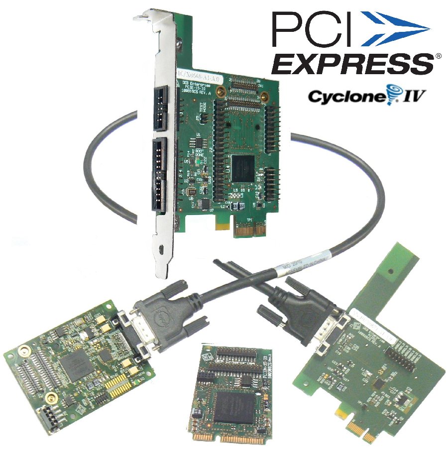
Currently, there are two most important PCIe extensions card available in the PCIe embedded application market: The first one is PCIe MiniCard that has a form factor smaller than standard PCIe board (about 30x50mm), the second one is the PCIe on cable, which allows to remote the PCIe pheripheral devices up to 7 meters from the host and without any software additon.
The MiniCard standard is also called Mini PCIe. The Minicard format has a small form factor board and is used to implement the PCI Express interface on remote interface. The card size is 30mm wide by 50.95mm long by 5mm high. The Minicard uses a 52-pin card edge connector, the card pins are PCB fingers placed at the smallest edge of the card.
PCI Express Mini Card (also known as Mini PCI Express, Mini PCIe, and Mini PCI-E) is a replacement for the Mini PCI form factor based on PCI Express. Its standard has been developed by the PCI-SIG organization. The host device supports PCI Express and USB connectivity, and each card can be used in both ways. There is a 52 pin edge connector, made of two staggered rows on a 0.8 mm pitch. Each row has 8 contacts, a contact-less gap of 4 contact spaces, then a further 18 contacts. A half-length card is also specified 30×26.8 mm. The cards have a thickness of 1.0 mm (excluding components). Typical applications are in all types of remote I/O controller with Industrial Motherboard SBC (Mini-Itx, 3.5 SBC).

PCI Express External Cabling (also known as External PCI Express or Cabled PCI Express) specifications were released by the PCI-SIG in February 2007. Standard cables and connectors have been defined for ×1, ×4, ×8, and ×16 link widths, with a transfer rate of 500 Mbyte/s per lane. PCI Express Cable is a standard developed by the PCI-SIG to transmit the host PCI Express bus over a high-speed cable. This can be done internal to a system enclosure or external in a box-to-box type application. Using a PCIe cable is possible to extend the PCI Express bus up to seven meters from the host CPU complex and without any circuity for suppressing the inherent noise. Transmitting the host bus over copper cables opens a new world to the embedded designer. The PCIe Cable allows splitting the host PCIe environment by the remote embedded I/O subsystems one. Moreover, the PCIe cable allows different form factors for both the host and I/O subsystem and according to their specific system requires. For example, a high-end, dual Intel Xeon class host system can provide the user with the computing power and a high-speed data link to a high-end embedded I/O subsystem based on MicroTCA, PC/104, 3U CompactPCI Express, or proprietary form factor.


